Developed Software Interfaces
Several PC interfaces to measurement instruments (GPIB/RS232) and power electronics converters (USB/RS232) were developed at ApECOR to help in the development and evaluation of power electronics systems. Examples are shown below.
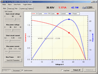
Solar Array Simulator Interface
- GPIB connection to Agilent solar array simulator (SAS)
- The following solar array parameters can be configured:
Open circuit voltage (Voc), maximum power voltage (Vmp), short circuit current (Isc), maximum power current (Imp) - Display of I/V and P/V curve as well as the current operating point on both curves
- Preview of I/V and P/V curve is shown if any of the 4 parameters is changed
- Macro mode: Records and plays a series of operating conditions; interval, transition time and step size is adjustable
- Data logging and plotting: All 4 parameters and the operating points can be logged and displayed over time
- Table mode of SAS: Program non-ideal SAS curves
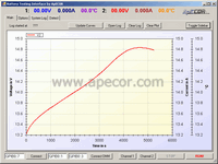
Battery Testing Interface
- GPIB connection to Hameg HM8142 power supply and Agilent 34401A digital multimeters
- Great for testing different battery charge algorithms, especially if source power is variable such as solar or wind power and Nickel-based batteries need to be charged accurately
- 2 Channels: Run and compare tests for 2 batteries simultaneously
- Maximum ratings per channel: 0..30V/0..1A; voltage or currents limits can be set anywhere within the ranges
- Measurement of voltage, current and temperature (if battery equipped with sensor)
- Main configuration options: Charge time, relax time, charge current, measurement interval
- Lots of advanced options: Variable charge times and currents (specify min. / max. value and step size), generation of random charge currents
- Parallel or series configuration of the 2 channels to allow higher currents or voltages for one battery
- Data is saved automatically and can be reopened and plotted for later evaluation
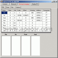
Efficiency Measurement Automation
- GPIB connection to 4 Agilent 34401A digital multimeters
- Easily test efficiency of your power electronics converters
- Measures input/output voltage/current with an adjustable interval
- Displays voltages, currents, calculated powers and efficiency in real-time
- Data recording and saving to a file with a click of a button
- Any recorded data can be plotted versus output power
- Recorded data can be reopened and plotted for later review
- Warning levels can be specified; if reached, interface will show a red background of respective value and multimeter will beep
- Current measurements require accurate current sense resistors, scale and offset can be input in interface
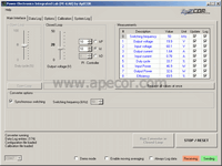
Power Electronics Converter Interfaces
- USB/RS232 connection to DSP of power electronics converter
- Controls the operation of the converter and read ADC measurements from the DSP
- Main controls are: Turn converter on & off, set voltage and/or current limits in closed loop, set duty cycle in open loop
- Advanced controls: Change controller type and gains, switching frequency
- Measurements: Reads the ADC values from the DSP and displays the data in a table
- Calibrate the interface with the specific hardware connected: Enables correct display and set points for voltages and currents
- Data logging and plotting over time
- Automatic storage: Data log can be opened and plotted for later evaluation
General requirements to connect to instruments are:
- PC with Microsoft Windows and the Microsoft .NET Framework Version 2.0
- Agilent IO Control
- Instruments with GPIB/RS232 interfaces
- USB/GPIB adapter such as Agilent 82357
- PC with Microsoft Windows and the Microsoft .NET Framework Version 2.0
- DSP with serial interface and programmed with our communication library
- Serial-to-USB adapter (can be included on DSP board)
Please contact ApECOR to discuss your custom interfacing requirements.
This is a no-obligation service, whereby ApECOR's engineers can assess your proposed specifications and give a price quotation.


